Database diagrams
Right-click a database object and select Diagrams | Show Diagram
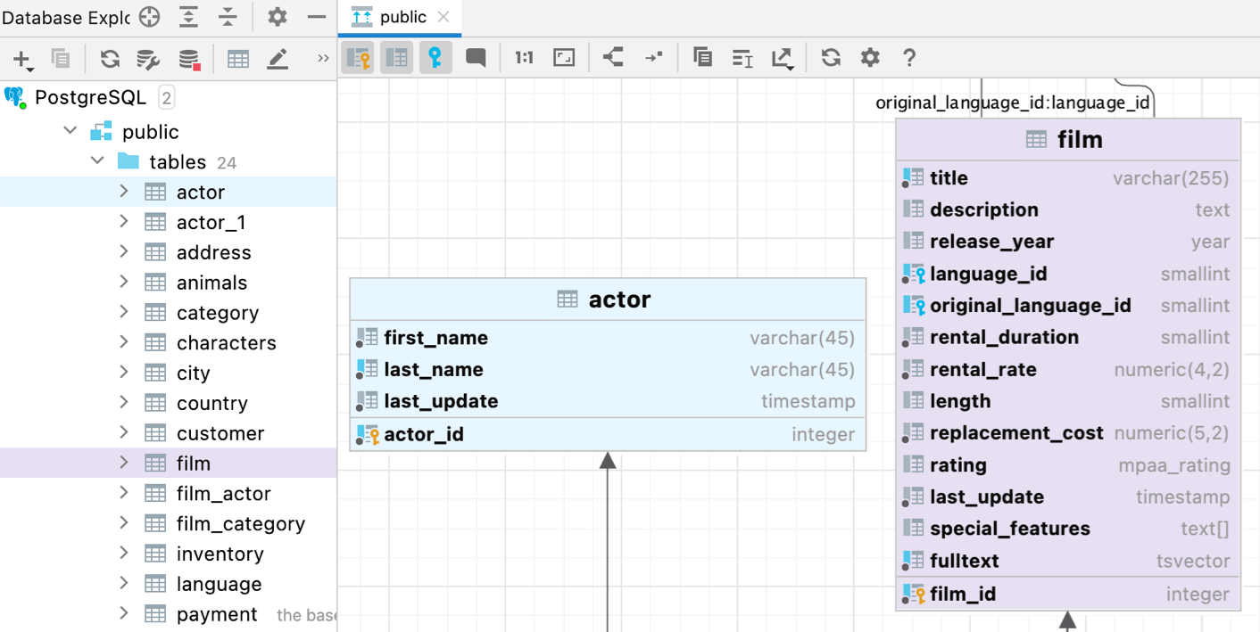
Database diagrams graphically show the structure of the database and relations between database objects. You can generate a diagram for a data source, a schema, or a table. To create relations between database objects, consider using primary and foreign keys.
The following video gives a short overview of diagrams in DataGrip.
You can save the generated diagrams in two formats: UML and PNG. The UML format is an internal format developed specifically for DataGrip. It is not supported by other products. If you want to share the created diagram, consider using PNG.
Also, you can build execution plans. Execution plan is a set of steps that were used to access data in a database. For more information about creating an execution plan, refer to Visualize a query plan.
To pan and zoom the diagram, use your touchpad, scroll bars or the mouse wheel for vertical scrolling and + mouse wheel for horizontal scrolling. You can also use + mouse wheel for zooming.
To use the magnifier tool, keep the key pressed, and hover your mouse pointer over the desired areas of the diagram. Use the mouse wheel to extra zoom the diagram area within magnifier tool.
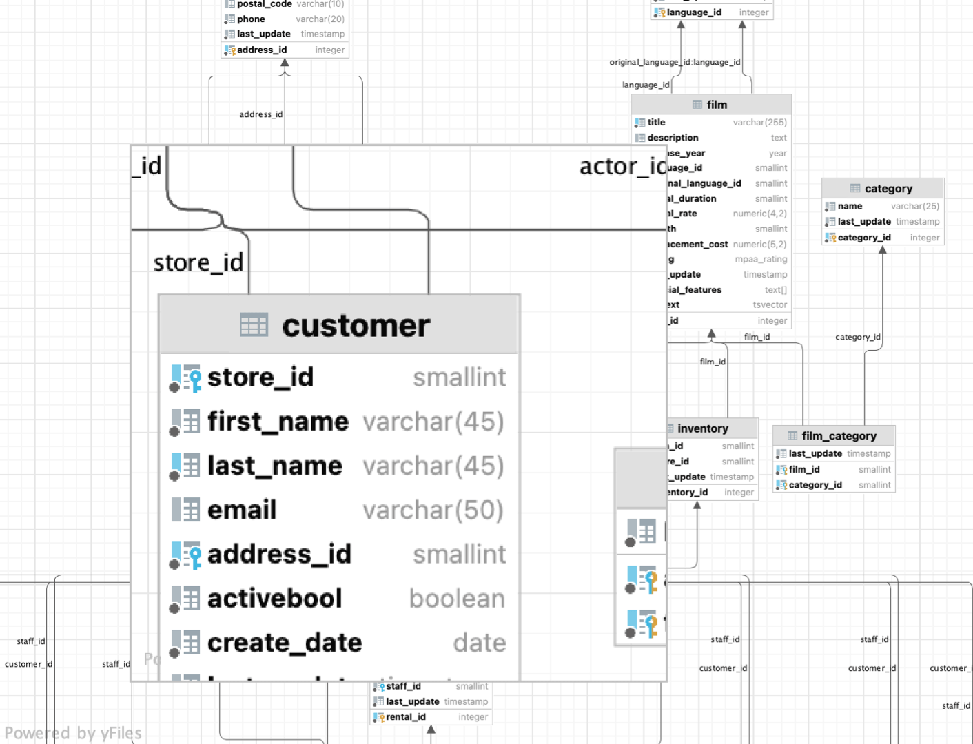
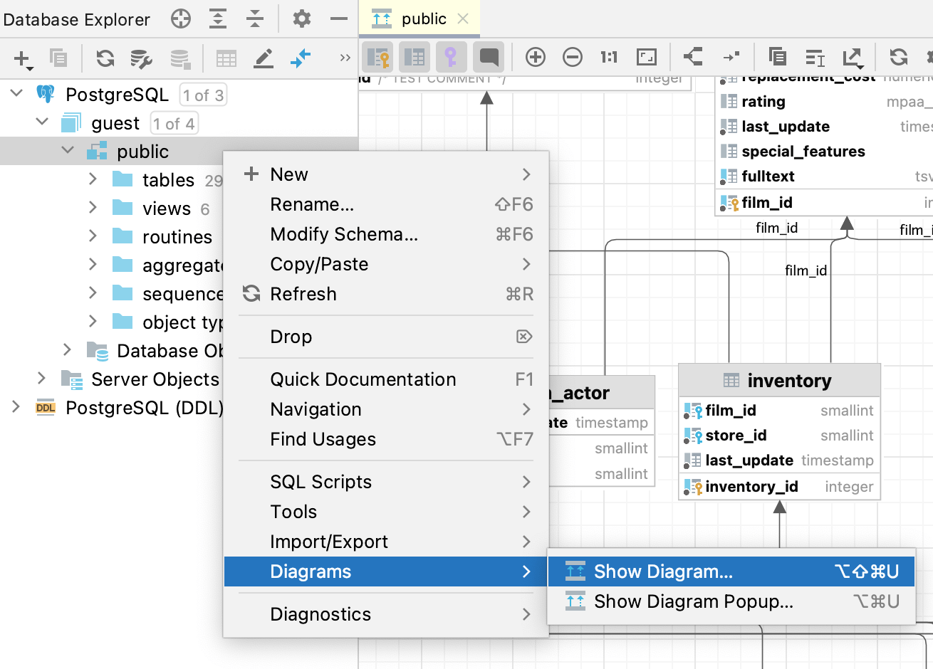
In the Database Explorer ( View | Tool Windows | Database Explorer) , right-click a database object and select Diagrams | Show Diagram.
Generate a diagram. For more information about generating a diagram, see Generate a diagram for a database object.
Click the Comments button (
).

In the Database Explorer ( View | Tool Windows | Database Explorer) , right-click an object and select Tools | Set Color….
Select a color and click OK.
This UML format is an internal format supported only by DataGrip.
Right-click a diagram and navigate to Export Diagram | Export to File | IDEA .uml.
To open the saved diagram, drag the UML file to the editor.
Right-click a diagram and select Export Diagram | Export to Image.
The Analyze Graph action group lets you analyze the graph in various ways such as perform auto clusterization, measure the node centrality, search cycles, filter path between two nodes, and so on.
Most of the time, generated diagrams are big and complicated. Typically, you want to concentrate only on the specific part of the diagram. DataGrip lets you filter paths between two diagram elements.
In the diagram editor, select two nodes on which you want to focus and right-click one of them to open the context menu.
From the context menu, select Analyze Graph | Focus On Paths Between Two Nodes.
note
If you want to focus not only on just two nodes, but on how the selected node is connected with its neighbors, select the Focus on Node Neighborhood option from the context menu.
In the dialog that opens, select additional options if needed and click Find.
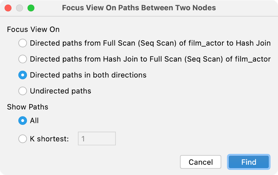
DataGrip displays connections associated only with the selected nodes.
You can use this action to identify the important nodes in the graph.
In the diagram editor, right-click anywhere in the editor to open the context menu.
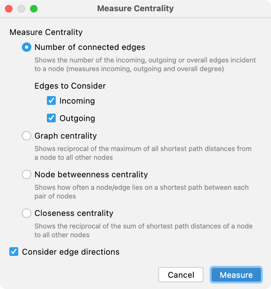
From the context menu, select Analyze Graph | Measure Centrality.
In the dialog that opens, select additional options if needed and click Measure.
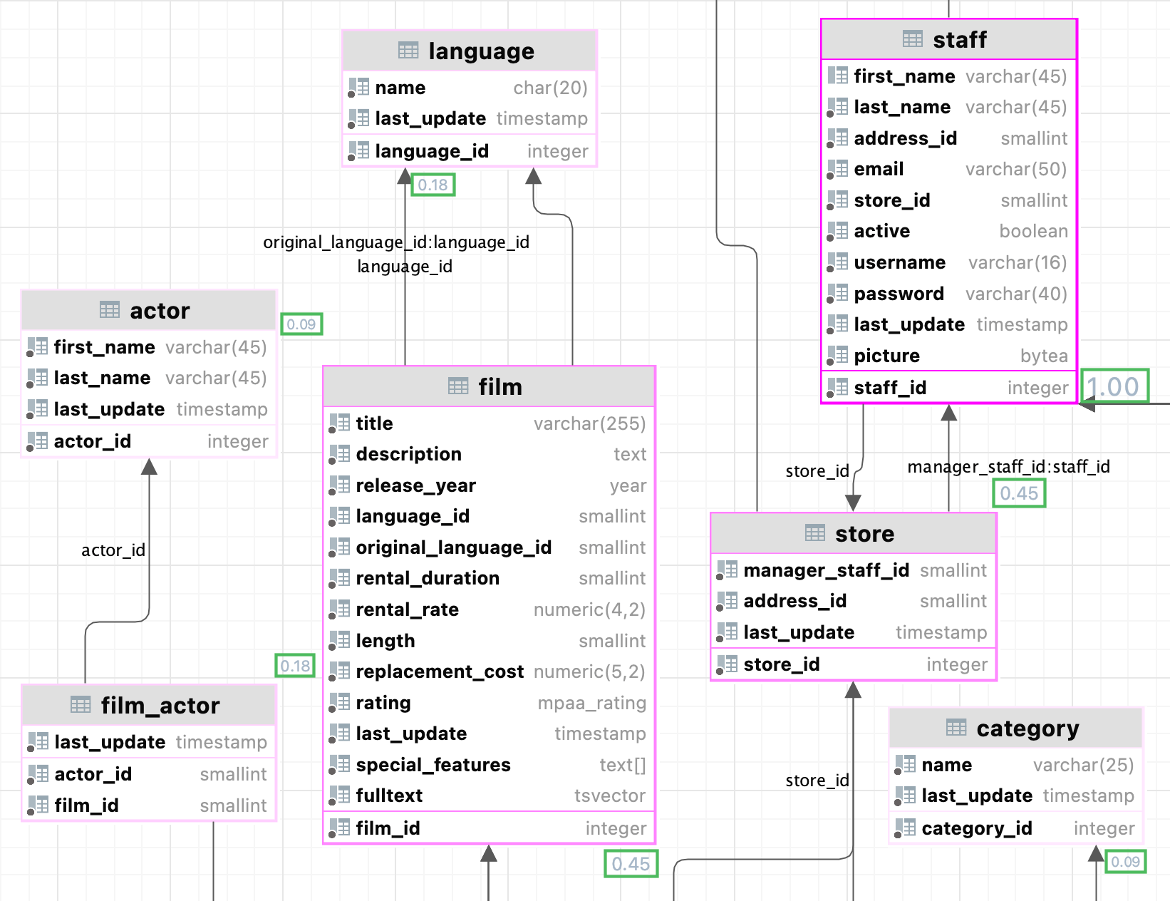
The node "importance" is expressed via fractional value from 0.0 to 1.0 measurement and the brightest node selection should be explored first.
tip
Press to cancel the actions.
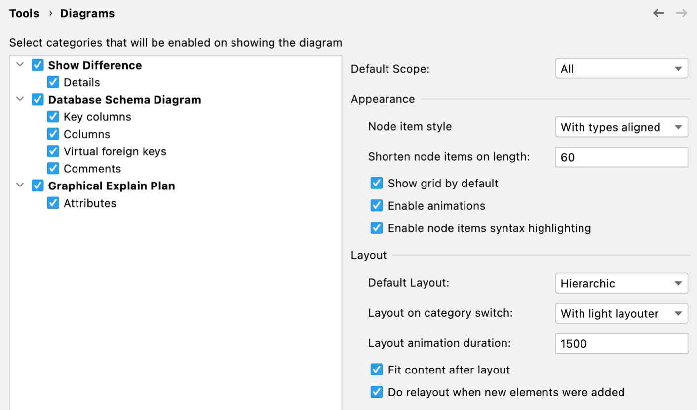
To configure the default visibility settings and layout for diagrams, open settings by pressing and navigate to Tools | Diagrams.
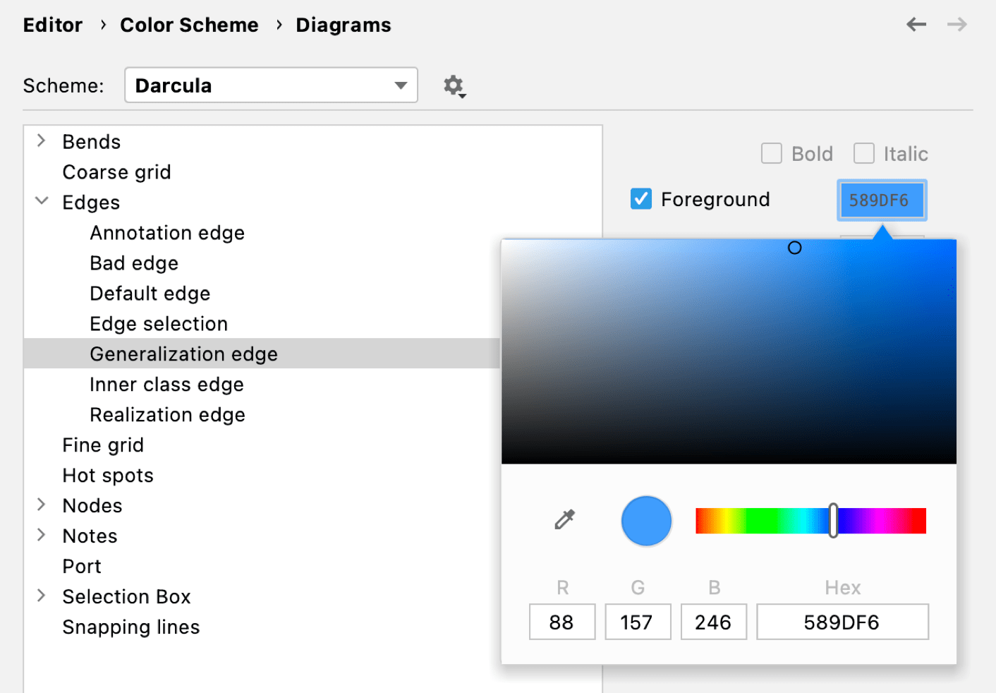
Open settings by pressing and navigate to Editor | Color Scheme | Diagrams.
Click Edges//Generalization edge.
Click the color picker near the Foreground checkbox.
Select the checkboxes next to the elements to be shown on diagrams.
Item | Description |
|---|---|
Show Difference | |
Details | If this checkbox is selected, all the specified details of the elements will be shown in the UML class diagram for a revision. If this checkbox is not selected, only node elements will be included in the diagram. |
Database Schema Diagram | |
Key columns | For the primary key columns to be shown when a diagram opens, select this checkbox. When viewing a diagram in the editor, use |
Columns | For the columns other than the primary key columns to be shown when a diagram opens, select this checkbox. When viewing a diagram in the editor, use |
Graphical Explain Plan | |
Attributes | Toggles the display of query attributes on a query map. These attributes can be a number of rows, index names, or any other additional information about the query.  |
Item | Description |
|---|---|
Default layout | Select the desired layout from the Default layout list. Node elements in newly created diagrams will be arranged according to the selected layout. |
Default scope | Select scope from the Default scope list. Specifying a scope helps you avoid showing in diagram the unnecessary hierarchies. You can define scopes for your project in the Scopes page of the Settings () dialog. |
Fit content after layout | If this checkbox is selected, then after applying a layout selected on the diagram context menu, all diagram elements will be resized to fit into the current diagram area. In diagram, use the |
Do relayout when new elements were added | If this checkbox is selected, diagram layout will be performed automatically after adding new elements. |